
The production of pump rotor manufacturing components requires a delicate balance between complex geometry and strict mechanical tolerances. As global demand for high-viscosity fluid transport increases, the industrial sector is shifting away from traditional milling toward high precision thread whirling. This guide explores the technical nuances of rotor thread whirling, providing a data-driven roadmap for optimizing throughput and cost effectiveness.
The Geometry Challenge: Achieving Eccentric Precision in Rotor Production
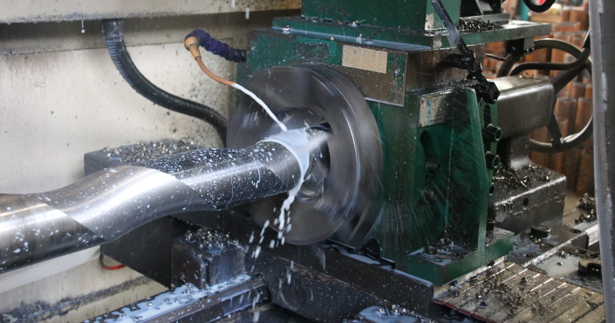
Achieving high precision in progressive cavity pump (PCP) rotors requires managing the relationship between eccentricity and the helical lead. Rotor thread whirling addresses these challenges by utilizing a synchronized, multi-cutter head that compensates for tool pressure, ensuring consistent thread pitch even in slender, vibration-prone workpieces.
The fundamental difficulty in pump rotor manufacturing lies in the rotor’s eccentricity ($e$). Unlike standard cylindrical threads, a PCP rotor is an eccentric screw that must maintain a perfect interference fit with its stator. Any deviation in the cross-sectional symmetry or the helical path leads to premature stator wear and hydraulic inefficiency.
Managing Thread Pitch Accuracy and Lead Deviations
In long-form rotor production (often exceeding 5000mm), the “Slenderness Ratio” becomes a critical failure point. Traditional CNC machining methods often struggle with tool deflection because the cutting force is concentrated on a single point. Whirling machines solve this by distributing cutting forces across multiple inserts—typically 6 to 12—within a rotating ring.
- Vibration Dampening: The tangential entry and exit of the whirling cutters create “comma-shaped” chips, which significantly reduce the radial pressure exerted on the rotor.
- Lead Consistency: By maintaining constant material support through guide bushing (in Swiss-style setups) or high-rigidity steady rests, lead deviations are kept within ±0.01mm per meter of length.
Thread Whirling vs. CNC Milling: The Cost-Effectiveness Benchmark
Comparing thread whirling to conventional cnc machining reveals a 3x to 5x increase in throughput. Whirling machines offer superior cost effectiveness by completing the profile in a single pass, eliminating secondary grinding, and extending tool life through improved heat dissipation during the cutting external threads process.
For years, CNC milling was the standard for thread machining in the pump industry. However, as material requirements shifted toward hardened tool steels and stainless alloys (HRC 30-45), milling became a bottleneck due to excessive cycle times and heat-induced warping.
Throughput Analysis: Reducing Cycle Times with Multi-Cutter Whirling Heads
A side-by-side comparison of thread machining technologies demonstrates why high-volume manufacturers are pivoting to whirling.
| Metric | CNC Thread Milling | Thread Whirling (SG/Whirl Series) |
| Machining Passes | 3–5 (Roughing + Finishing) | 1 (Single Pass) |
| Cycle Time | 100% (Baseline) | 25% – 35% |
| Surface Finish (Ra) | 1.6 – 3.2 $\mu m$ | 0.4 – 0.8 $\mu m$ |
| Tool Life | Moderate (Heat concentration) | High (Interrupted cutting cooling) |
| Setup Complexity | Low | Medium |